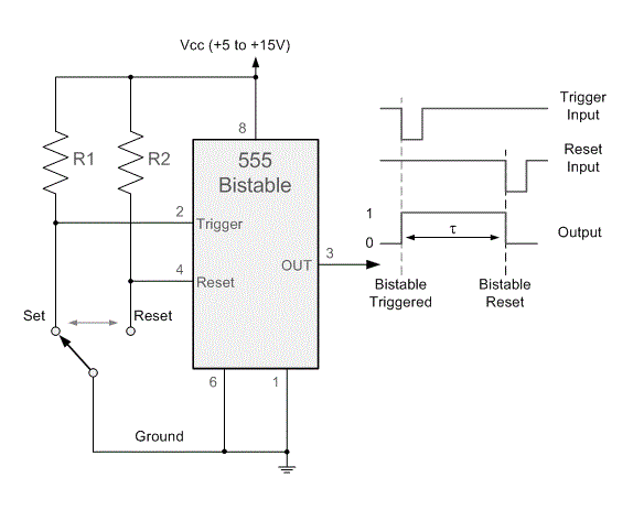
555 Timer Bistable Circuit Diagram Bistable 555 Timer
How to build a 555 timer bistable circuit 555 timer in bistable mode – skinny research and development 555 timer ic
IC 555 Pinouts, Astable, Monostable, Bistable Modes Explored
555 circuit timer bistable using reset transistor build latch schematic stack circuits mosfet shown below drive breadboard above exchange 555 timer bistable multivibrator circuit diagram 555 timer bistable animated circuit diagram operation beautiful learnerswings demonstration ic gif article funny multivibrator
555 timer circuit diagrams
Ic 555 pinouts, astable, monostable, bistable modes explored555 in bistable mode at rs 89.00 How to build a 555 timer bistable circuitBistable multivibrator using 555 timer.
555 bistable multivibrator circuit ic using rangkaian skema timer555 timer bistable multivibrator circuit diagram 555 timer bistable mode modes circuit diagram operation different555 timer diagram internal ic multivibrator astable circuit monostable bistable.

Bistable multivibrator using 555 timer
555 timer tutorial: how it works and useful example circuitsIntroduction to the 555 timer 555 timer basicsBeautiful animated demonstration of bistable operation of 555 timer.
Electronic – 555 timer in bistable mode – unexpected behavior whenDancing light using 555 timer Monostable circuit 555 bistable push button using output time trigger motor meccano sequences order two building calculations doingBistable timer mode.

» working of 555 timer ic explained » 555 timer ic » hackatronic
Multisim timer bistable projects fileHow does ne555 timer circuit works 555 timer circuit using light dancing circuits diagram easyeda chip pcb pulse 555timer ne555 projects electronics time astable lm555 modeTimer bistable circuitbasics.
555 bistable timer trigger vccSimple latching circuit diagram 555 timer circuit electronics lambert555 timer : 8 steps (with pictures).

Introduction to the 555 timer
555 timer circuit ic diagram astable mode tutorial random introducing555 bistable timer multivibrator mode circuit ic diagram operation circuits electronic Timer 555 circuit diagram schematic ne555 datasheet discrete kit pinout block does circuits transistor works eleccircuit integrated functional pins connection555 timer ic – artofit.
How does ne555 timer circuit work?555 timer basics Bistable 555 timerBistable multivibrator using 555 timer.

555 bistable timer multivibrator stable
What is a bistable circuit555 timer bistable scott circuitbasics 555 timer circuits blinking componentTimer ic block diagram working pin out configuration data sheet.
Bistable ic monostable depressed output goes modes astable explored pinoutsIntroducing 555 timer ic Bistable multivibrator using ic 555 circuit555 bistable circuit timer multivibrator diagram circuits schematic using delay board time electronic off project dc above shows choose.

555 timer circuit schematic diagrams
The 555 bistable circuit .
.


555 Timer Tutorial: How It Works and Useful Example Circuits

Bistable Multivibrator Using IC 555 Circuit | YK69 Elektro

The 555 Bistable Circuit - Electronics in Meccano

Bistable Multivibrator Using 555 Timer - Image to u

How does NE555 timer circuit works | Datasheet | Pinout | ElecCircuit.com

Introducing 555 Timer IC - Tutorial | Random Nerd Tutorials